
Membrane Switch Cure
By Mike Walters
www.mysterycircuits.com
mike@mysterycircuits.com
Part 1
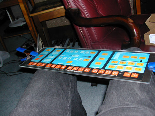
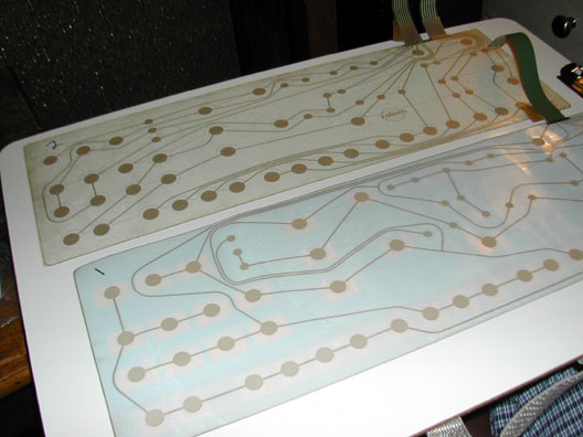
First I peeled the top surface of the membrane off the synthesizer, and laid them out on a non-porous surface for marking everything. With both surfaces facing the same direction, I numbered all the switches. See the Pin Outs page for switch numbers per each parameter.
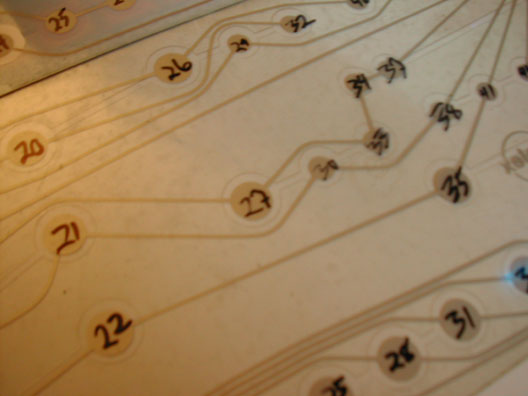
I wrote the numbers with a sharpy directly on the surface of each switch:
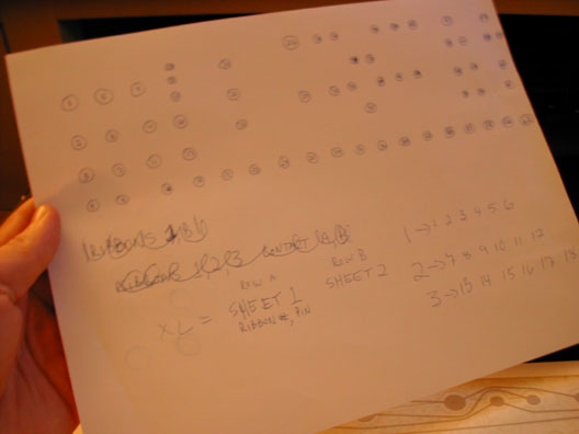
Using an Excel spreadsheet, I entered what parameter went with each number, and left two blank spaces for tracing the pin outs. Again, please refer to the Pin Outs page to see the exact data.
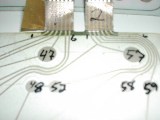
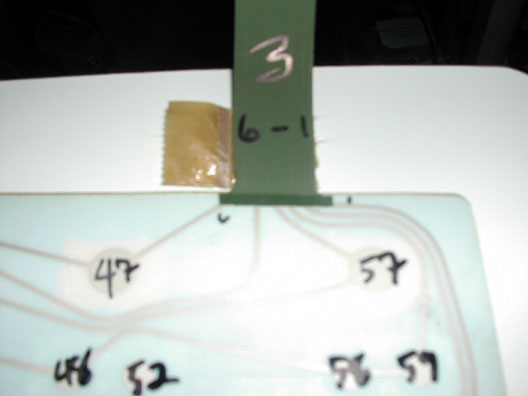
VERY IMPORTANT!! Notice how I wrote 1-6 on Ribbon 1, 1-6 on Ribbon 2, and 6-1 on Ribbon 3. Ribbon 3 should have been numbered the same way as 1 and 2, but I didn't do that. According to my data for the switch matrix, Ribbon 3 is still reversed. Just play along until the end. When you finally wire the new wires in place of Ribbon 3, you have to reverse them! Otherwise it won't work!
Once everything was labeled, I began tracing each and every switch to its proper pin. For an easy visual look at the two above pictures- Switch 47 goes to Ribbon 1, Pin 4. On the other panel, switch 47 goes to Ribbon 3, Pin 6. That's how I entered all the data.
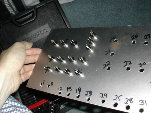
After I was finally done, I was ready to mount the original membrane panel onto its new surface. I used a piece of welders sheet I bought from the hardware store. Before I drilled the holes for the new switches, I had to find the right position that wouldn't block any numbers or words for the functions. They still had to be intuitive, but not right on the old tops. Later, you'll see pictures up close where I chose to drill the holes. After the holes were drilled, I wrote the corresponding switch numbers on the welders sheet.